 english
 français
 Deutsch
 Italiano
 Русский
 Español
 português
 Nederlandse
 ελληνικά
 日本語
日本語
 한국
한국
 العربية
 हिन्दी
 Türkçe
 indonesia
 tiếng Việt
 ไทย
ไทย
 বাংলা
বাংলা
 فارسی
فارسی
 polski
Quick Link
Quick Contact
Address
Liando U Valley 25#, No.423, Juyang Rd, Huangdao District, Qingdao, 266425,China
Tel
86-532-68977475
Our Newsletter
Subscribe to our newsletter for discounts and more.

1 Introduction Uav target jamming equipment is a professional control equipment that transmits high-intensity electromagnetic waves to operate on the flight control system and satellite positioning receiver of various small and medium-sized civil UAVs, and disables them by blocking normal communicat...
Uav target jamming equipment is a professional control equipment that transmits high-intensity electromagnetic waves to operate on the flight control system and satellite positioning receiver of various small and medium-sized civil UAVs, and disables them by blocking normal communication signals.
This product can interfere with 800MHz ~ 6000MHz full-band flight control signals and GPS/GLONADD/ Beidou II maintenance and positioning signals to block their communication.
800 MHZ to 6000 MHZ.
Block interference.
Broadband noise frequency modulation, frequency sweep, comb spectrum, extensible.
40MHz, 80MHz, cocoa expansion.
20 w or less.
Acuity 1.5 km.
Level: -180° ~ 180°;
Pitch: 0°~60°.
Level: 0.01° ~ 45°/S;
Pitch: 0.01° ~ 15°/S.
-25℃~+40℃.
Voltage: DC28V (with AC220 integrated PSU);
Power consumption: 200W.
Ethernet, 100Mbps.
25 kg or less.
528mm x 590mm x 460mm (L x W x H).
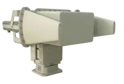
The UAV target jamming equipment is mainly composed of jamming host, intelligent head and 800MHz ~ 6000MHz antenna array.
The UAV target jamming device generates one or two excitation signals for navigation and remote control diagram signals through signal excitation board, outputs to the power amplifier module, and radiates out through directional jamming antenna. The signal excitation board is mainly composed of FPGA and AD9361 chip. The FPGA is controlled to generate interference excitation signals with different bandwidth and different modulation styles through control commands, and then the excitation signals are sent to the power amplifier module to transmit the interference signals through the antenna.
The flow chart of signal realization of interference suppression function is shown in figure. The control command of the interference device is sent to the gimbal control system through the output of the man-machine interface to control the rotating of the gimbal. At the same time, the gimbal forwards the parameters to the signal excitation board to generate the excitation signal, and the control power amplifier module starts to work at the same time.
The interference host adopts the modular design concept, which is mainly composed of signal excitation module, circuit breaker, 800MHz ~ 6000MHz power amplifier module group and PSU module.
The basic block diagram of the signal excitation module is shown in the figure. The intelligent cradle head forwards the control parameters of the signal excitation module sent by the terminal computer, and the baseband signal required by the FPGA chip production is transmitted to the frequency conversion output on the AD9361 chip.
5.1.2 800MHz ~ 6000MHz power amtion moduleplifier module group design
The 800MHz to 6000MHz power amplifier module group is designed in piecewise mode. There are 800MHz to 6000MHz power amplifiers and 1100MHz to 1600MHz power amplifiers.
F2:1600MHz to 6000MHz.
800MHz~1600MHz antenna array adopts segmented design, which are 800MHz~1600MHz log-periodic antenna and 1600MHz~6000MHz horn antenna.
0.8~1.6GHz interference antenna adopts logarithmic period antenna, the structure size of antenna is shown.
1600MHz~6000MHz interference antenna adopts horn antenna, the structure size of antenna is shown.

