Model F3X122MI High Accury There-axis Fiber Optic Gyroscope With 0.5 °/hr Bias Drift
1.Product Brief
1.1 Working Principle and Function of Products
This product is a three-axis angular rate inertial sensor, which consists of three single-axis fiber optic gyroscopes with a single light source and electronic circuit.
Two beams from a laser are injected into the same fibre but in opposite directions. Due to the Sagnac effect, the beam travelling against the rotation experiences a slightly shorter path delay than the other beam. The resulting differential phase shift is measured through interferometry, thus translating one component of the angular velocity into a shift of the interference pattern which is measured photometrically.
Beam splitting optics launches light from a laser diode into two waves propagating in the clockwise and anticlockwise directions through a coil consisting of many turns of optical fibre. The strength of the Sagnac effect is dependent on the effective area of the closed optical path: this is not simply the geometric area of the loop but is enhanced by the number of turns in the coil.
1.2 Configuration
1.2.1 Components
Optical part: light source (three Fogs use one single light source), fiber coils, coupler, phase modulator, optical-to-
electrical converter
Circuit part: preamplifier, AD convertor, digital signal processor, DA convertor, output interface and light source control
unit.
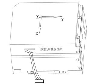
1.2.2 Outline size: 122 mm×103 mm×71mm

1.2.3 Weight:1050 ± 50g
1.3 Performance
Range of measured angular rate(º/s): ±1201
Bias(º/h): -3 ~ +3
Bias drift(10s,1σ)(º/h): ≤0.5
Bias repeatability(1σ)(º/h): ≤0.5
Bias at changing temp(º/h)(-40~+60°C): ≤5
Bias magnetism sensitivity(º/h/Oe): ≤0.5
Scale factor(sp/º/s): 2200 ~ 2600
Scale factor change at full
temperature(-40~+60°C)
(ppm): ≤5000
Scale factor repeatability(1σ)(ppm): ≤200
Scale factor non-linearity(ppm): ≤200
Scale factor asymmetry (ppm): ≤200
Startup time(min): ≤15
Threshold(º/h): ≤0.5
Dead zone(º/h): ≤1.0
Resolution(º/h): ≤0.5
Bandwidth(Hz): ≥100
Output delay time(ms): ≤2
Maximum start-up angular rate(º/s): ±120
Random Walk Coefficient(º/h1/2): ≤0.05
1.4 Mechanical and electrical connections
1.4.1 Mechanical interface
Four M5 screw holes on the bottom, and two of them are positioning holes
1.4.2 Power consumptionthem are positioning holes

When the product works steadily, the power consumption is less than 7.5W.
| Voltage |
Voltage range |
Ripple |
Current |
| 5V |
±5% |
≤100mV |
≤3.00A(start-up) |
| ≤1.00A(working) |
| -5V |
±5% |
≤100mV |
≤1.00A(start-up) |
| ≤0.50A(working) |
1.4.3 Electrical interface
The product uses J30-21TJ 21-core socket to supply power and output data.
Fig 1. Definition for Model J30-21TJ connector
| Pin number |
Definition |
Remarks |
| 1 |
FOG_PX+ |
X Fog Positive Pulse Output(+) |
| 2 |
GND |
X Fog power supply ground |
| 3 |
FOG_PX- |
X Fog Negative Pulse Output(-) |
| 4 |
GND |
Y Fog power supply |
| 5 |
FOG_PY+ |
Y Fog Positive Pulse Output(+) |
| 6 |
+5V |
X Fog Power Supply +5V |
| 7 |
FOG_PY- |
Y Fog Negative Pulse Output(-) |
| 8 |
Empty |
|
| 9 |
FOG_PZ+ |
Z Fog Positive Pulse Output(+) |
| 10 |
TEMPER_Z |
18B20_Z Signal |
| 11 |
FOG_PZ- |
Z Fog Negative Pulse Output(-) |
| 12 |
GND |
Z Fog power supply |
| 13 |
+5V |
Y Fog Power Supply +5V |
| 14 |
GND |
(3 in 1)18B20_XYZ power supply ground |
| 15 |
+5V |
Z Fog power supply +5V |
| 16 |
+5V |
(3 in 1) 18B20_XYZ power supply +5V |
| 17 |
-5V |
X Fog power supply -5V |
| 18 |
-5V |
Y Fog power supply -5V |
| 19 |
-5V |
Z Fog power supply -5V |
| 20 |
TEMPER_Y |
18B20_Y Signal |
| 21 |
TEMPER_X |
18B20_X Signal |


 Your message must be between 20-3,000 characters!
 Please check your E-mail!
  Your message must be between 20-3,000 characters!
 Please check your E-mail!

