Model XB335 High Accury There-axis Fiber Optic Gyroscope With 0.5 °/hr Bias Drift
1.Product introduction
1.1 Working Principle and Function
This product is an inertial angular rate sensor based on the principle of Sagnac effect, which is used to measure the angular rate movement of the carrier around the sensitive axis of this sensor. This unit takes the fiber optic coil as the angular rate sensitive unit and the closed-loop detection circuit as the basis.
Two beams from a laser are injected into the same fibre but in opposite directions. Due to the Sagnac effect, the beam travelling against the rotation experiences a slightly shorter path delay than the other beam. The resulting differential phase shift is measured through interferometry, thus translating one component of the angular velocity into a shift of the interference pattern which is measured photometrically.
Beam splitting optics launches light from a laser diode into two waves propagating in the clockwise and anticlockwise directions through a coil consisting of many turns of optical fibre. The strength of the Sagnac effect is dependent on the effective area of the closed optical path: this is not simply the geometric area of the loop but is enhanced by the number of turns in the coil.
This product is an inertial sensor composed of optical system, corresponding power supply and data processing circuit. It can provide three-axis angle increment information.
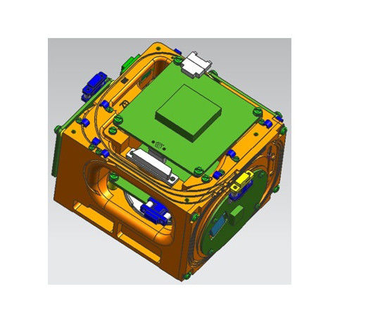
1.2 Configuration
The product is mainly composed of the following components:
a) Optical part: light source, coupler, Y modulator, fiber coil, detector;
b) Circuit part: processor board, light source board and preamplifier;
c) Structural part: body, cover, etc.
1.3 Shape and installation size
Overall dimensions:126.9 ± 0.1 mm ×112.4 ± 0.1 mm × 70 ± 0.1 mm,
Installation dimensions:85 ± 0.1 mm × 85 ± 0.1 mm,

1.4 Weight
1100g±50g
Including cable, connector, assembly screw, light source board, gyro control circuit, platform body and other accessories directly attached to the gyro.
1.5 Performance parameters
| Project |
Performance indicators |
|
Standby time
(s)
|
≤5 |
Warm up time
(min) |
≤1 |
Range of measured angular rate
(°/s) |
±400 |
Absolute value of zero deviation
(normal,°/h) |
≤10.0 |
Bias Drift at fixed temperature
(10s,1σ) |
≤0.5 |
Bias Drift at full temperature
range from -40℃ till 60℃
(10s,1σ) |
≤3.0 |
|
Total temperature zero deviation
(°/h)
|
≤10.0 |
Bias Drift Repeatability at full
temperature range from-40℃ till 60℃
(°/h)(1σ) |
≤0.5 |
|
Random walk
(°/h)
|
≤0.05 |
Scale factor asymmetry
(ppm) |
≤200 |
|
Scale Factor Non-linearity at full temperature
range from -40℃ till 60℃
(ppm)
|
≤150 |
|
Scale Factor Repeatability at full temperature
rangge from -40℃ till 60℃
(ppm)(1σ)
|
≤200 |
|
The total temperature scale factor is
extremely poor
(ppm)
|
≤200 |
|
The threshold value
(°/h)
|
≤0.5 |
|
Resolution
(°/h)
|
≤0.5 |
|
Bandwidth
(Hz)
|
≥200 |
|
Zero bias sensitivity
(°/h/Gs)
|
≤0.2 |
|
Zero bias temperature sensitivity
(°/h/℃)
|
≤0.05 |
| Scale factor nominal value |
0.2"/pulse |
|
Scale factor temperature sensitivity
(ppm/℃)
|
≤50 |
| Error angle of input axis(absolute value) |
30' |
| Input shaft misalignment Angle repeatability |
5" |
1.6 Mechanical and electrical interface relationship
1.6.1 Mechanical interface
The mounting surface of the product constitutes the fixed surface for external installation. The mounting screw is M6.
1.6.2 Power requirements
XB335 high precision fiber optic gyro is powered by 5V dc power supply
| Name |
Requirement |
| Control panel +5V |
Power consumption>5W |
The steady state current≤0.8A |
The transient current≤0.7A |
| Control panel -5V |
Power consumption>3W |
The steady state current ≤0.5A |
The transient current≤0.5A |
| The ligght source +5V |
|
The steady state current≤2A |
The transient current≤0.3A |
| The power supply ripple |
≤50mV Vpp |
|
|
|
Steady state power consumption
of the gyroscope
|
<7.5W |
|
|
| Maximun gyro power consumption |
<10W |
|
|
1.6.3 Electrical connection interface
The connector for external connection is J30-9ZKW-J or J30-9TJW-J.
J30-9TJW-J socket pin number definition
| Pin number |
The signal name |
Signal that |
| 1 |
GND |
Power supply (Ground wire) |
| 2 |
GND |
Power supply (Fround wire) |
| 3 |
GND |
Power supply (Ground wire) |
| 4 |
empty |
|
| 5 |
empty |
|
| 6 |
+5V |
Power supply +5V |
| 7 |
+5V |
Power supply +5V |
| 8 |
+5V |
Power supply +5V |
| 9 |
empty |
|
J30-9ZKW-J socket pin number definition
| Pin number |
The signal name |
Signal that |
| 1 |
T+ |
RS422 output(+) |
| 2 |
T- |
RS422 output (- ) |
| 3 |
GNDC |
empty |
| 4 |
GND |
Power supply (Ground wire) |
| 5 |
+5V |
Power supply +5V |
| 6 |
SYNC |
Sync signal |
| 7 |
+5VC |
empty |
| 8 |
GND |
Power supply (Ground wire) |
| 9 |
-5V |
Power supply - 5V |

 Your message must be between 20-3,000 characters!