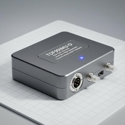
Small Size High Accuracy TDF99IMU-D Fiber Optic Inertial Unit
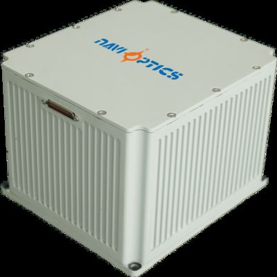
Fiber optic inertial units feature small size, light weight, low power consumption, and high accuracy. Designed for pure strapdown systems, they meet the requirements of unmanned platforms, water/torpedo weapons, and land, airborne, and missile weapon platforms that demand compact size and high-precision inertial measurement with dynamic angular and linear motion measurement capabilities.
Performance Specifications
Gyroscope Performance Indicators
| Project |
Content |
Index |
Notes |
| Zero bias indicator |
Zero bias stability (100s) |
0.005°/h |
|
| Zero bias stability (10s) |
0.01°/h |
|
| Variable temperature zero bias stability |
0.02°/h |
|
| Scale Factor |
Full temperature scale factor |
≤150ppm |
|
| Other indicators |
Random walk coefficient |
0.001°/√h |
|
| Input range |
|
400°/s |
|
Accelerometer Performance Indicators
| Project |
Content |
Index |
Notes |
| Deviation index |
Deviation monthly comprehensive error |
20μg |
|
| Zero bias indicator |
Zero bias temperature sensitivity |
20μg/℃ |
|
| Scale Factor |
Scale factor monthly comprehensive error |
20ppm |
|
| Scale factor temperature sensitivity |
20ppm/℃ |
|
| Range indicator |
Input range |
±20g |
|
Whole Machine Characteristics
| Project |
Content |
Index |
Notes |
| Environmental performance indicators |
Operation temperature |
-40℃~60℃ |
|
| Storage temperature |
-45℃~70℃ |
|
| General requirements |
Power supply |
18~36V(DC) |
|
| Stable power consumption |
≤15W |
Startup power consumption ≤ 25W |
Communication Protocols
The universal debugging interface communication protocol records data with a baud rate of 460800, 8 data bits, 1 stop bit, no checksum, and low to high order transmission. General debugging data includes IMU raw data, user command data, satellite navigation record data, and navigation result data.
| SN |
Message content |
Type |
Notes |
| 1~2 |
frame header |
char |
0x5A,0x54 |
| 3 |
frame length |
char |
0x1E |
| 4 |
Frame ID |
char |
0x04 |
| 5~8 |
Frame Number |
int |
200Hz accumulation |
| 9~11 |
X accelerometer output |
char*3 |
Note 1 |
| 12~14 |
Y accelerometer output |
char*3 |
|
| 15~17 |
Z accelerometer output |
char*3 |
|
| 18~20 |
X gyroscope output |
char*3 |
Note 2 |
| 21~23 |
Y gyroscope output |
char*3 |
|
| 24~26 |
Z-gyroscope output |
char*3 |
|
| 27 |
reserve |
char |
|
| 28~31 |
reserve |
int |
|
| 32~33 |
reserve |
short |
0x5A,0x54 |
| 34 |
checksum |
|
Total of 4-33 bytes |
Note 1: Calculation method for speed increment
(1) The 5ms velocity increment value output by the accelerometer at time tk is yk (unit: m/s);
(2) Define the initial value of speed increment accumulation SumVelInt=0;
(3) Define Yk=int [yk * 1e5+δ Yk-1], where int [*] represents rounding operation, and δ Yk-1 represents the remainder after rounding the velocity increment in the previous step;
(4) The remainder after rounding Yk: δ Yk=yk * 1e5+δ Yk-1-Yk;
(5)SumVelInt = SumVelInt + Yk;
(6) Integer range limitation for SumVelInt:
If SumVelInt ≥ 1e7, SumVelInt=SumVelInt -1e7;
If SumVelInt<0, SumVelInt=SumVelInt+1e7;
After integer processing, limit the range of SumVelInt values to [0,1e7);
(7) Send the last 3 bytes of SumVelInt after integer processing.
Note 2: Calculation method for angle increment
(1) The 5ms angular increment value of the gyroscope output at time tk is xk (unit: rad);
(2) Define the initial value SumAngInt for angle increment accumulation as 0;
(3) Define Xk=int [xk * 1e7+δ Xk-1], where int [*] represents the rounding operation, and δ Xk-1 represents the remainder after rounding the previous angular increment;
(4) The remainder after rounding Xk: δ Xk=xk * 1e7+δ Xk-1-Xk;
(5)SumAngInt = SumAngInt + Xk;
(6) The integer range limitation of SumAngInt:
If SumAngInt ≥ 1e7, SumAngInt=SumAngInt -1e7;
If SumAngInt<0, SumAngInt=SumAngInt+1e7;
After integer processing, limit the range of SumAngInt values to [0,1e7);
(7) Send the last 3 bytes of SumAngInt after integer processing.
Electrical Interfaces
External electrical interfaces include power interface, RS422 communication interface, and 100Mbps Ethernet interface. The socket model is J30JM-37ZKP, with matching plug model J30J-37TJL.
| Pin |
Connectivity |
Signal name |
Signal characteristics |
| 1,2 |
External power supply |
PCS power supply positive |
24V |
| 3,4 |
PCS power supply ground |
Power Ground |
|
| 5 |
200Hz signal output |
IMU_TX1+ |
IMU data output positive |
| 6 |
|
IMU_TX1- |
IMU data output negative |
| 9 |
Synchronization signal |
IMU_SYN+ |
IMU synchronization signal positive |
| 10 |
|
IMU_SYN- |
IMU synchronization signal negative |
Dimensions

Dimensions: 158mm * 161mm * 122.5mm (± 1mm, excluding connectors)
Installation size: 146mm * 149mm, installation aperture: 4- Φ 5.5mm
Weight: ≤ 3.6kg
 english
 français
 Deutsch
 Italiano
 Русский
 Español
 português
 Nederlandse
 ελληνικά
 日本語
日本語
 한국
한국
 العربية
 हिन्दी
 Türkçe
 indonesia
 tiếng Việt
 ไทย
ไทย
 বাংলা
বাংলা
 فارسی
فارسی
 polski